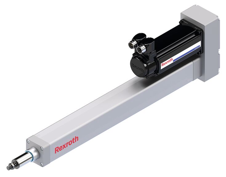
Electromechanical Cylinders (EMCs) are a high-performance alternative to traditional hydraulic and pneumatic cylinders. The EMC’s main component is the Ball Screw Assembly (BSA), which converts torque from the Servo Motor to linear motion. The drive nut on the BSA then actuates forward and backward along the shaft, without rotation. Thanks to Bosch Rexroth’s plethora of configuration options, the EMC can be configured to fit many applications, with a high level of energy and mechanical efficiency.
Here is a video displaying the assembly of an Electromechanical Cylinder:
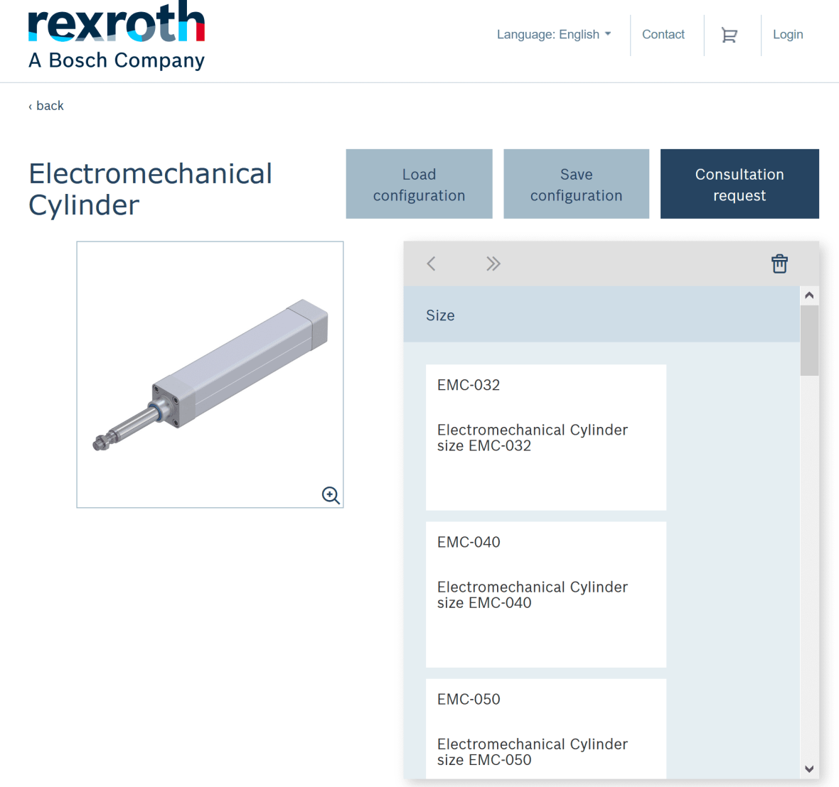
Bosch Rexroth has developed a convenient product configurator for most of their products, and the Electromechanical Cylinder is no different. A direct link to the product page for the EMC is found here. This page has summarized information for the EMC, lists primary features, technical data, mounting information, accessories, and ordering codes. A similar page exists for a heavy duty EMC if that is what your application requires.
Figure 1: EMC Configurator
Screenshot retrieved from Configurator at https://www.boschrexroth.com.
The EMC configurator gives a number of options to customize a cylinder for your need. The options include:
EMC Size
Max stroke
Housing
Tolerance grade
Preload
Lubrication
Sensor profile
Number of Sensors
1st, 2nd, 3rd, and 4th sensor options
Version
Ratio
Mechanical interface
Motor code
Motor connection
Motor brake
Motor
Motor plug location
Documentation
Mounting Elements
CAD options
Piston rod position
After a configuration is complete, models of the configured part can be downloaded and opened in CAD software like Solidworks to be added to an assembly. A consultation request will also be submitted so that the customer can speak to a Bosch Rexroth representative about their configuration.
Pricing
If this is a product that can be useful for your Senior Design Project, please contact a Bosch Rexroth representative here for more information. Pricing can be determined on a case-by-case basis.
Electromechanical Cylinder Product Theory
The Electromechanical Cylinder is a specialty electronic device developed by Bosch Rexroth. The EMC is a precision linear actuator whose main purpose is linear motion and can be applied in a wide range of applications.
Structural Design
The Electromechanical Cylinder is made up of a Ball Screw Assembly with a piston rod attached to the screw drive nut, with everything sealed inside of a metal housing. A servo motor or other driving mechanism is attached on the screw end of the Ball Screw Assembly to provide the torquing motion. As the screw shaft rotates, the drive nut from the Ball Screw Assembly moves up and down along the shaft, resulting in the linear motion of the piston rod extending and retracting. One particular configuration option of the EMC can add limit switches to the interior of the EMC, which can help prevent damage during operation.
Advantages of the Electromechanical Cylinder
The Bosch Rexroth website advertises a multitude of advantages to using the Electromechanical Cylinder over other available options on the market:
High performance and cost effectiveness from the Ball Screw Assembly technology
Wide configuration options and modularity
Low design and implementation costs for customers because the EMC comes preassembled
Smart programmable drive system allows for complex travel profiles
Lubrication options minimize maintenance
IP65 protection and chemical resistant options available to increase hygiene
Applications of the Electromechanical Cylinder
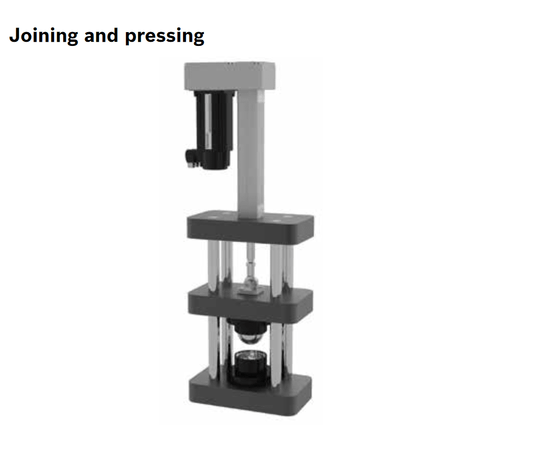
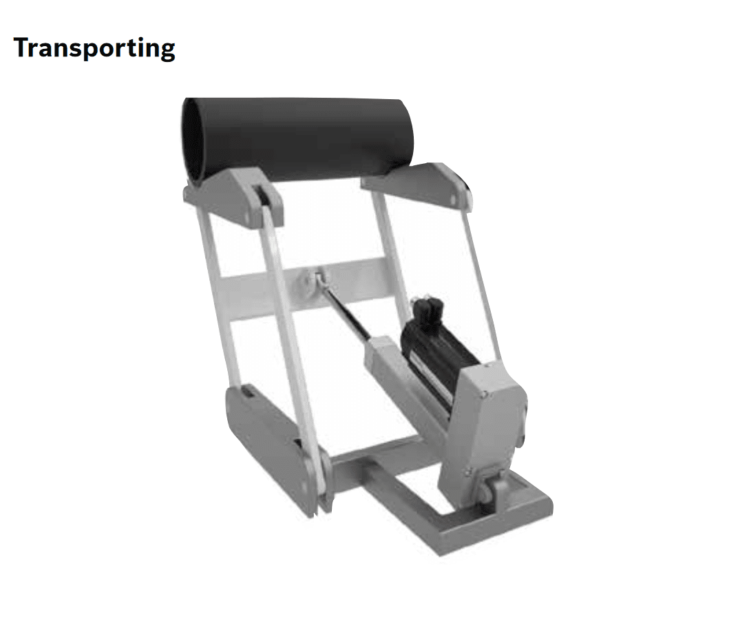
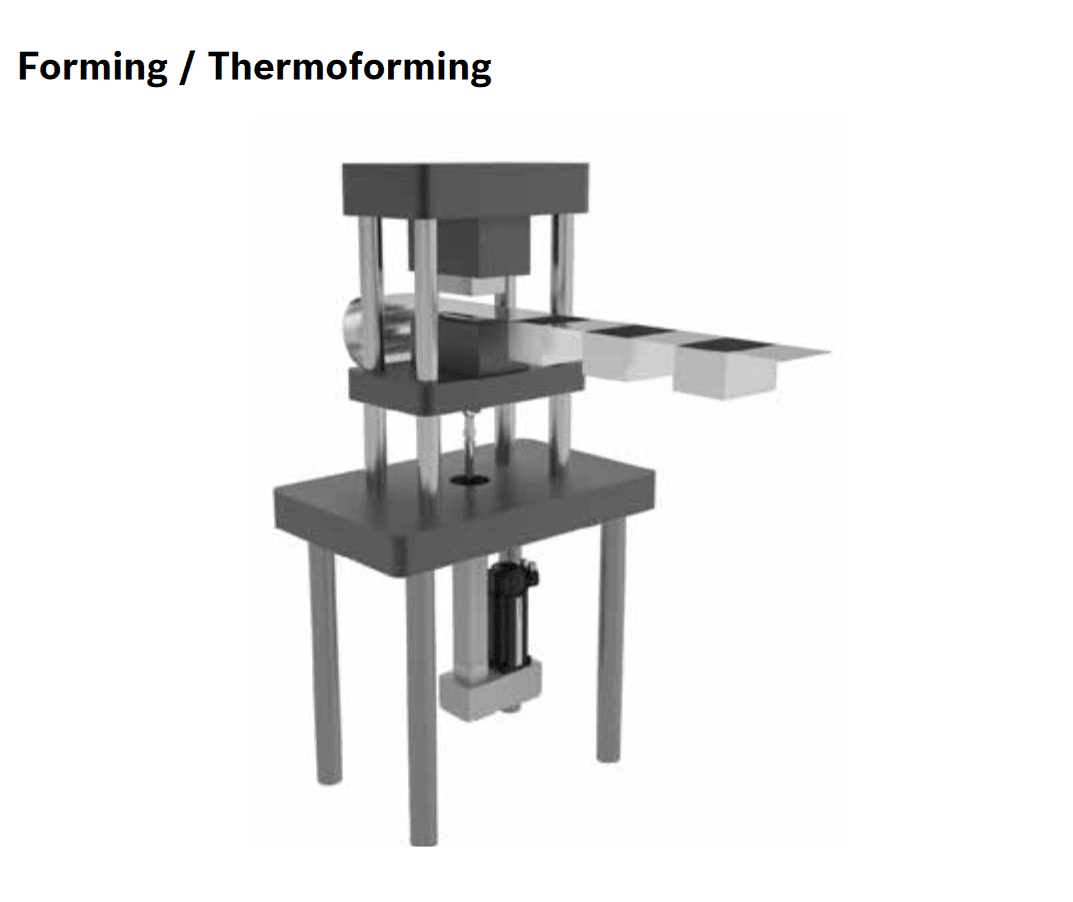
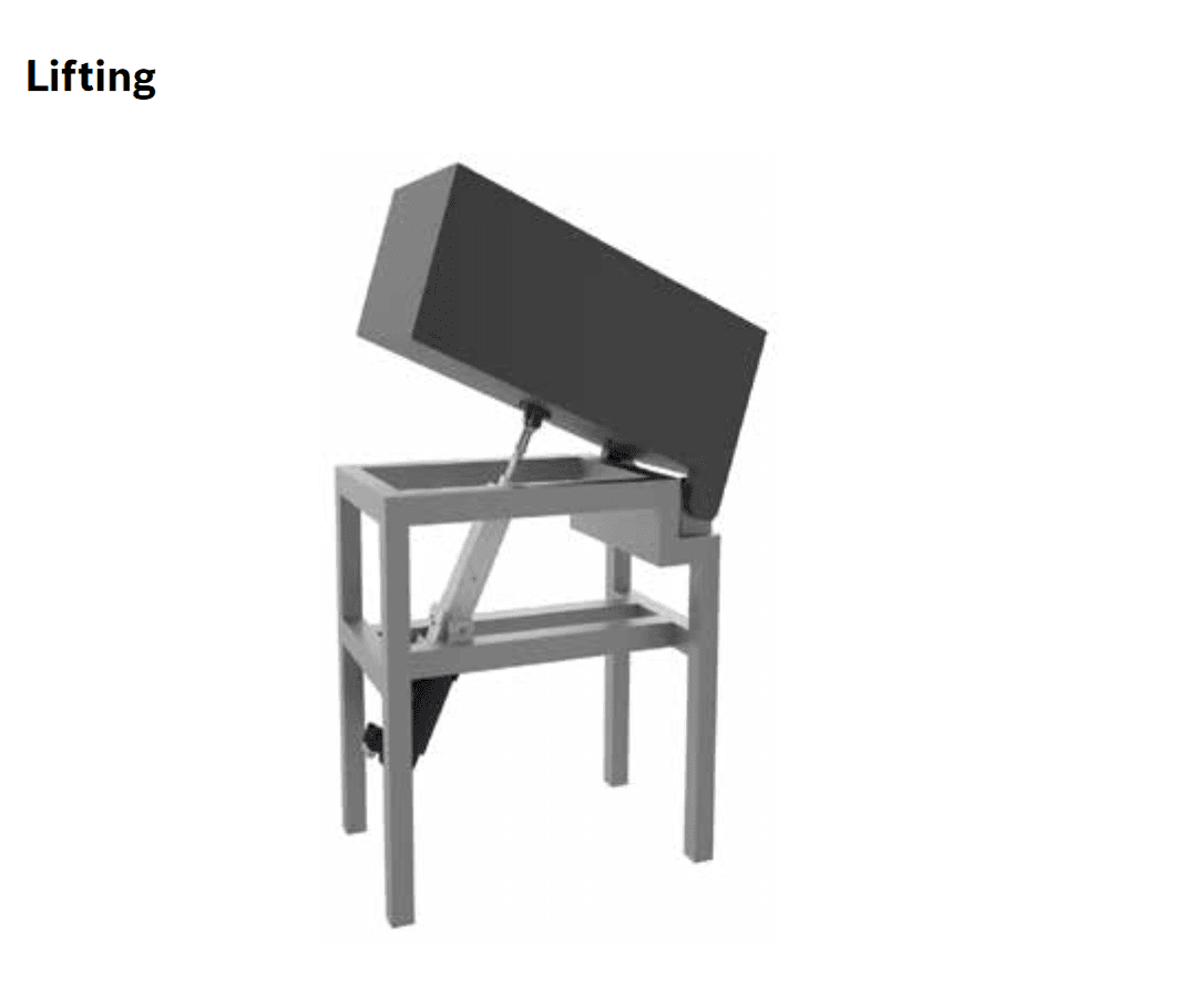
Electromechanical Cylinders are advantageous in many applications due to their size, accuracy, and programmability. The high configurability of the EMC can result in quite compact cylinders that can fit in tight spaces. Without providing an exhaustive list of applications, some examples from the EMC catalog include joining and pressing, transporting, forming, and lifting. Pictures of these applications are shown below:
Figure 1: Joining and pressing application of an EMC
Figure 2: Transporting application of an EMC
Figure 3: Forming application of an EMC
Figure 4: Lifting application of an EMC
All pictures retrieved from the EMC Product Catalog at https://www.boschrexroth.com.
The Electromechanical Cylinder Product Catalog identifies and suggests four main parameters when considering what configuration of EMC is best suited for a particular application. Those four parameters are the application’s load, dynamics, geometry, and environmental conditions. It is important to completely define the application of the EMC before making a purchasing decision due to its specialized nature.
Load
Various loads surrounding the EMC need to be considered when picking an appropriate configuration:
The amount of force required for the process
The mass of the objects being worked on
The external forces on the EMC itself
Duty cycle of the EMC
Servicing requirements for the lifetime of the EMC
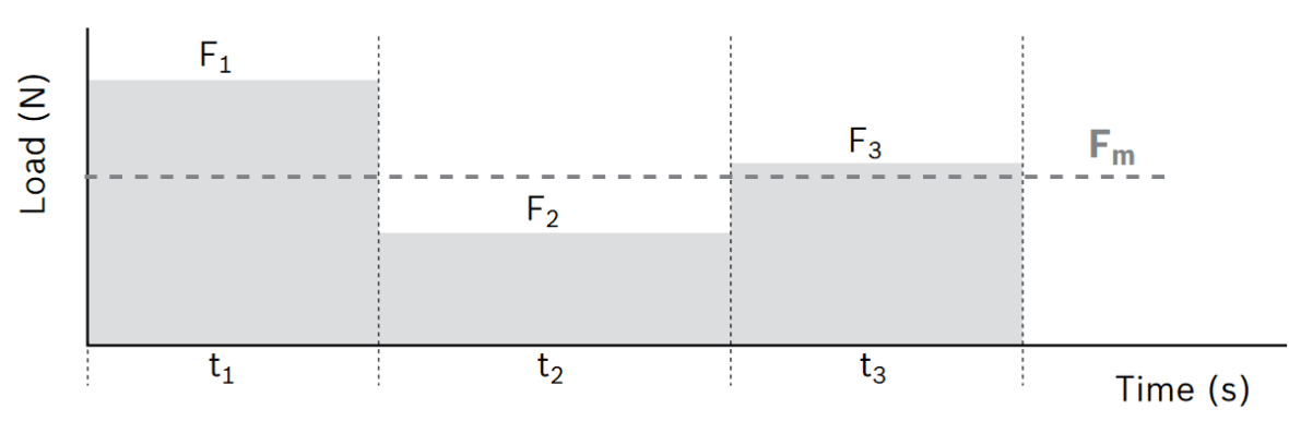
Characterizing the way the force changes over the cycle of motion is an important factor when determining the average force over one entire cycle of the piston rod. One warning that Bosch Rexroth gives when defining the application is that large factors of safety relating to the forces required should be avoided to ensure that the internal axis of the EMC is not over-sized. An example graph of required forces over an arbitrary EMC cycle is shown below.
Figure 1: Arbitrary loads as a function of time
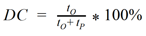
Another one of the more important sub-parameters of loads to consider is the duty cycle of the EMC. Duty cycle is the percentage of time where the EMC is active compared to the total time of the cycle. Duty cycle is important to help determine the life expectancy of the EMC, as well as the life expectancy of the individual components. The duty cycle for any operation, relating to an EMC or not, can be calculated using the following equation:
where DC is duty cycle in percent, t_O is operating time in seconds, and t_P is pause time in seconds.
Dynamics
The intended motion of the EMC and piston rod need to be considered when selecting a configuration:
Acceleration of the rod
Travel speed of the rod
Cycle time of the rod
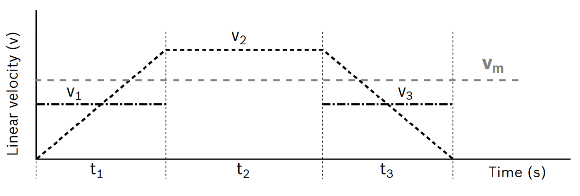
Similarly to the duty cycle, the characteristics of the EMC as a whole over the entire cycle, operating or pausing, need to be considered. The cylinder itself and drive device selected for the application can be better configured to maximize cost efficiency and performance if the entire cycle is defined. An example graph of linear velocity of the EMC as a function of time to describe an entire arbitrary cycle is shown below.
Figure 2: Arbitrary linear velocity as a function of time
Geometry
The geometry of the EMC and how it will fit and interact with the space it is used in needs to be considered when completing a configuration:
Work space
Installation space
Maximum required length of actuation
Interfering elements
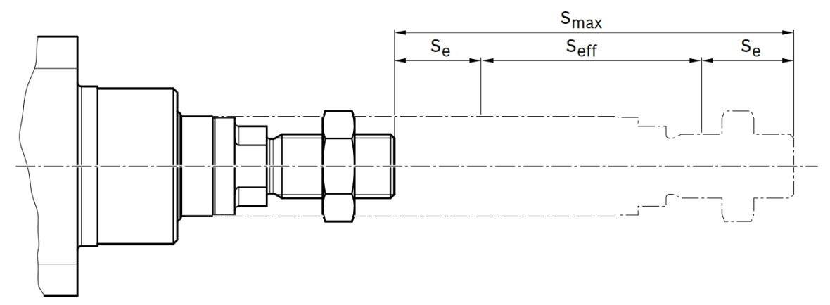
When determining the maximum travel range of the EMC, it is important for the lifespan of the product to not design the EMC to travel to the absolute end of the internal mechanical stop. A travel buffer should be included in the design at both the maximum extension and retraction of the stroke. The effective operating stroke and designed stroke buffer at both ends should total to the maximum stroke when placing the order. A diagram highlighting this suggestion is shown in the figure below.
Figure 3: Maximum stroke as a summation of effective and buffer lengths
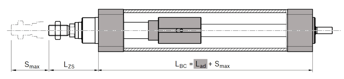
Due to the structure of the cylinder, the total length of the EMC is longer than the maximum stroke. This should come as no surprise, as the screw drive nuts and bearings need to be included in the total length. A diagram with an internal view into an EMC is shown in the figure below, with S_max signifying the maximum stroke, L_ZS representing the position of the piston rod when fully retracted, L_ad identifying the length of internal components of the EMC, and L_BC describing the length of the body of the cylinder.
Figure 4: Internal view of EMC
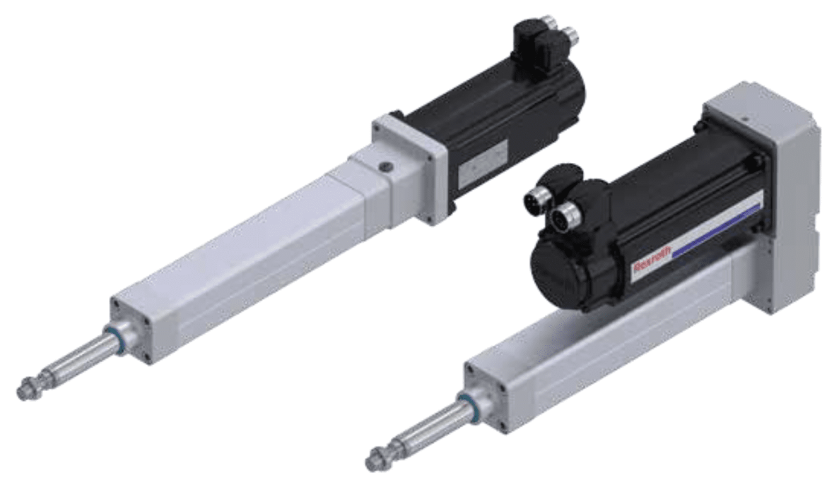
One more decision to make when considering the geometry of the EMC is the positioning of the motor on the end of the cylinder. Two options are available: either mounting the motor colinearly and coupling the motor shaft, or mounting the motor parallel to the axis and using a belt to connect the motor shaft and the Ball Screw Assembly. Both configurations are shown in the picture below, with the colinear option on the left and the parallel option on the right.
Environmental Conditions
Lastly, another parameter that needs to be considered when configuring the EMC are the environmental and installation conditions that the cylinder will be subject to:
Installation position
Mounting options
Degrees of freedom and motion
Temperature and humidity
Contamination and hygiene
Vibrations
When installing the EMC, the technician should be careful of applying transverse forces and distortive stress on any part of the cylinder. The piston rod especially is susceptible to damage, and any alignment errors can shorten the lifespan of the product. The type of attachment and fastening element for the EMC have an impact on the maximum permissible axial load as well. For more information about loads and fastening elements, please refer to the “Attachments and accessories” section in the EMC Product Catalog linked above. The environment that the EMC will be functioning in has a deterministic impact on the lifespan of the cylinder. Extreme temperatures, debris, and chemicals can have a serious impact on the seals, lubricant, and overall performance of the motor and screw drive if not serviced properly. All pictures retrieved from the EMC Product Catalog.