Sensors

Accelerometers

Accelerometers are devices that measure acceleration, which is the rate of change of the velocity of an object. They measure in meters per second squared (m/s2) or in G-forces (g). A single G-force for us here on planet Earth is equivalent to 9.8 m/s2, but this does vary slightly with elevation (and will be a different value on different planets due to variations in gravitational pull). Accelerometers are useful for sensing vibrations in systems or for orientation applications
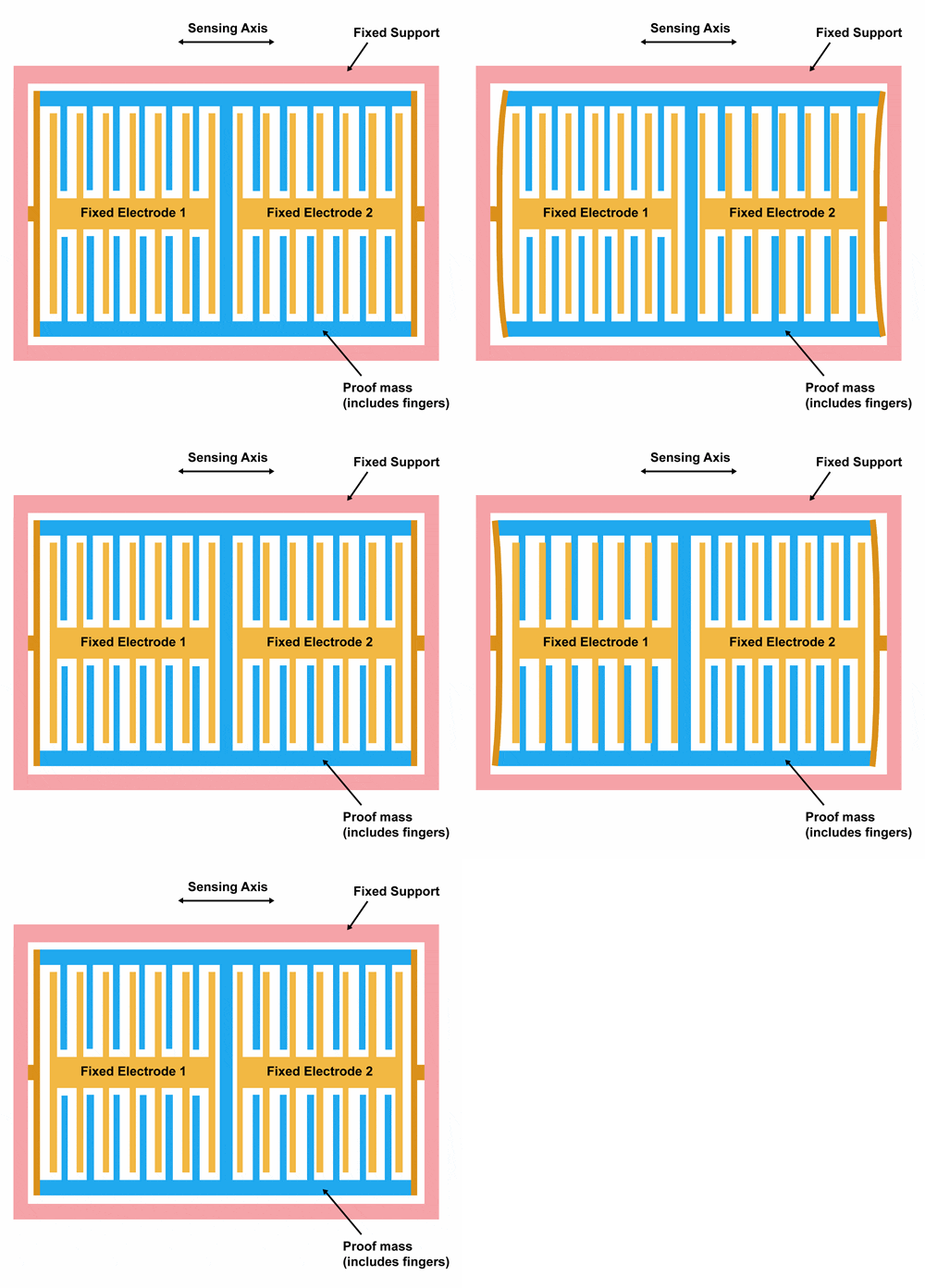
Accelerometers are useful for sensing vibrations in systems or for orientation applications

Link:https://www.siliconsensing.com/technology/mems-accelerometers/

An accelerometer is a device that measures the vibration, or acceleration of motion of a structure. The force caused by vibration or a change in motion (acceleration) causes the mass to “squeeze” the piezoelectric material which produces an electrical charge that is proportional to the force exerted upon it. Since the charge is proportional to the force, and the mass is a constant, then the charge is also proportional to the acceleration.
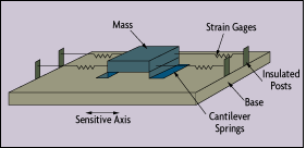
An accelerometer is a device that measures the vibration, or acceleration of motion of a structure

Link:https://www.omega.com/prodinfo/accelerometers.html

Theory

There are two types of piezoelectric accelerometers (vibration sensors). The first type is a “high impedance” charge output accelerometer. In this type of accelerometer, the piezoelectric crystal produces an electrical charge which is connected directly to the measurement instruments. The charge output requires special accommodations and instrumentation most commonly found in research facilities. This type of accelerometer is also used in high-temperature applications (>120C) where low impedance models cannot be used.
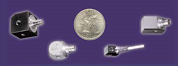
This type of accelerometer is also used in high-temperature applications (>120C) where low impedance models cannot be used.

Link:https://www.sensorsmag.com/components/principles-piezoelectric-accelerometers

The second type of accelerometer is a low impedance output accelerometer. A low impedance accelerometer has a charge accelerometer as its front end but has a tiny built-in micro-circuit and FET transistor that converts that charge into a low impedance voltage that can easily interface with standard instrumentation. This type of accelerometer is commonly used in industry. An accelerometer power supply like the ACC-PS1, provides the proper power to the microcircuit 18 to 24 V @ 2 mA constant current and removes the DC bias level, they typically produce a zero-based output signal up to +/- 5V depending upon the mV/grating of the accelerometer.
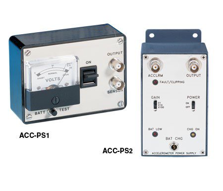
mV/grating of the accelerometer.

Link:https://www.omega.com/pptst/ACC-PS1_ACC-PS2.html

Application

Most piezoelectric accelerometers are made of quartz crystal, piezoelectric ceramics, or, for high-temperature operation, tourmaline or lithium niobate. They obey Newton’s second law, F = ma, in that the force acting on the measuring element is directly proportional to the acceleration produced. Available in a wide range of configurations and operating specifications, these devices are used wherever shock or vibration is of interest. Piezoelectric measuring systems are active electrical systems. That is, the crystals produce an electrical output only when they experience a change in load? they cannot perform true static measurements. However, it is a misconception that piezoelectric instruments are suitable for only dynamic measurements. Quartz transducers, when paired with adequate signal conditioners, offer excellent quasi-static measuring capability. There are countless examples of applications where quartz-based sensors accurately and reliably measure quasi-static phenomena for minutes and even hours. There are two types of piezoelectric sensor: high and low impedance. High-impedance units have a charge output that requires a charge amplifier or external impedance converter for charge-to-voltage conversion. Low-impedance types use the same piezoelectric sensing element as high-impedance units and also incorporate a miniaturized built-in charge-to-voltage converter. They also require an external power supply coupled to energize the electronics and decouple the subsequent DC bias voltage from the output signal.

Design

Piezoelectric sensors for measuring pressure, force, and acceleration may be regarded as underdamped, spring-mass systems with a single degree of freedom. They are modeled by the classical second-order differential equation whose Solution:
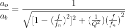
differential equation
  • fn = undamped natural frequency(Hz)
  • f = frequency at any given point of the curve(Hz)
  • ao = output acceleration
  • ab = mounting base or reference acceleration(f/fn=1)
  • Q = factor of amplitude increase at resonance
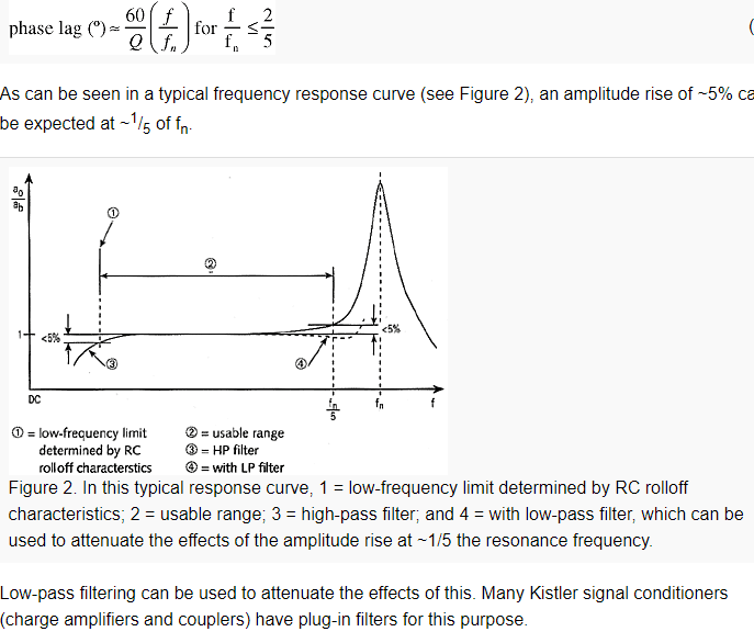
frequency response curve

References

GPS

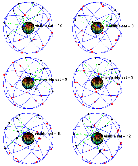
gps

image source https://learn.sparkfun.com/tutorials/gps-basics/how-does-gps-work

GPS stands for Global Positioning System, and it a systems for positioning and navigating in real time on a global scale. GPS is an all-weather, full-time, high-precision satellite navigation system developed by the US Department of Defense. It can provide global users with low-cost, high-precision navigation information such as three-dimensional position, speed and precise timing. The application model of satellite communication technology in the field of navigation has greatly improved the level of formalization of the earth society and effectively promoted the development of the digital economy. 

Basic Theory

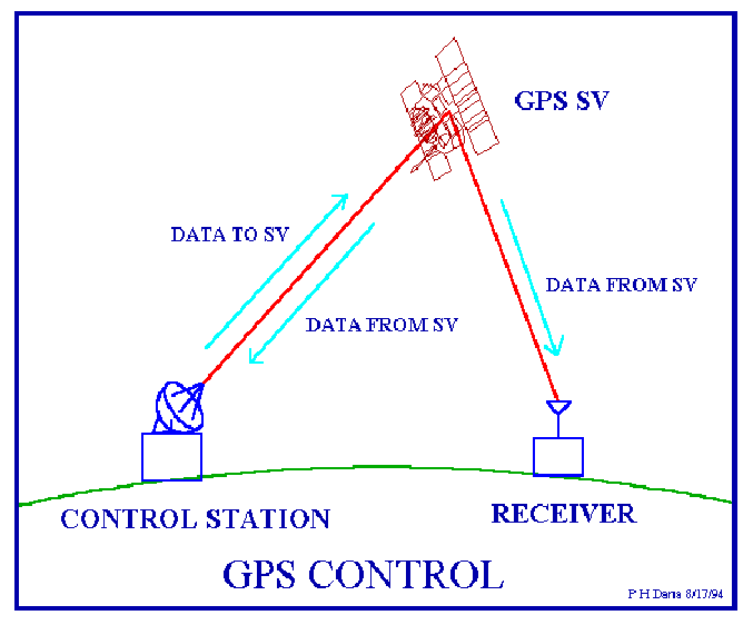
GPS control

Image sorce:http://www.geo.upm.es/postgrado/CarlosLopez/materiales/cursos/www.ncgia.ucsb.edu/giscc/units/u017/u017_f.html

The basic principle of GPS navigation system is to measure the distance between the satellite with a known position and the receiver of the user and then synthesize the data of many satellites to know the specific position of the receiver. To achieve this goal, the position of the satellite can be found in the ephemeris according to the time recorded by the satellite clock. The distance from the user to the satellite is obtained by recording the time the satellite signal travels to the user and multiplying it by the speed of light. According to the instantaneous position of the satellite moving at high speed as the known starting data, the method of spatial distance resection is used to determine the position of the point to be measured. As shown in the figure, it is assumed that the GPS receiver is placed on the ground to be measured at time t, and the time Δt at which the GPS signal arrives at the receiver can be determined, and other data such as the satellite ephemeris received by the receiver can be determined Applications The application of GPS in road engineering is mainly used to establish various road engineering control networks and to measure the external control points of aerial surveys. With the rapid development of high-grade highways, higher requirements are put forward for surveying technology. Because the length of the line is long, there are few known points. Therefore, it is difficult to meet the requirements of high precision by conventional measurement methods. GPS technology is also used in the control measurement of extra large bridges. Since it does not need to be viewed, it can form a strong mesh shape, improve the accuracy of the point, and is also very effective for detecting the fulcrum of the conventional measurement. GPS technology also has broad application prospects in tunnel measurement. GPS measurement does not need to be viewed, which reduces the intermediate links of conventional methods. Therefore, it has high speed and high precision and has obvious economic and social benefits. GPS and electronic maps can be used to display the actual position of the vehicle in real time, and can be arbitrarily enlarged, reduced, restored, and changed; can be moved with the target to keep the target on the screen; multi-window, multi-vehicle, multi-screen track at the same time.

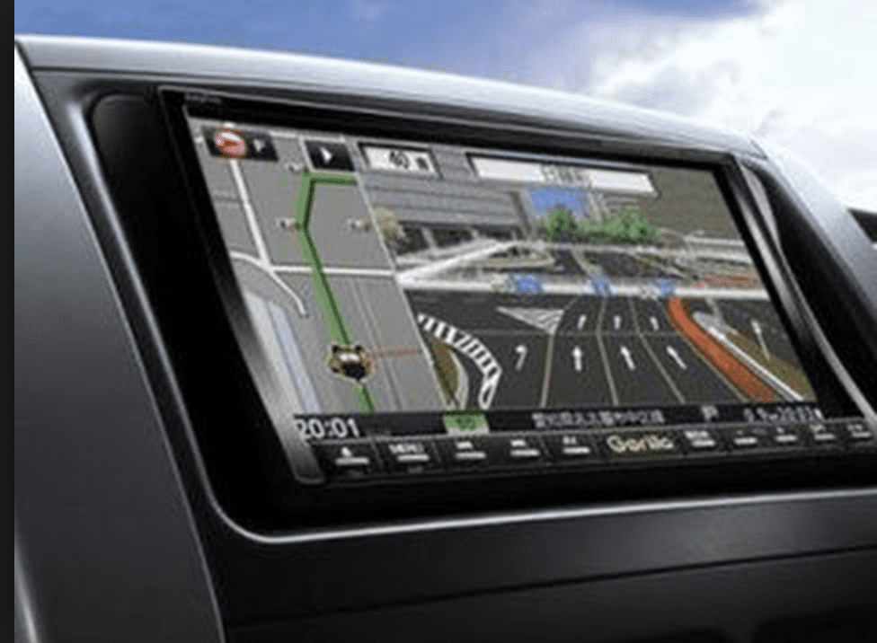
gps tracker

Image Source: https://www.wired.com/2017/02/waze-cars/

Providing travel route planning is an important auxiliary function of car navigation systems, including automatic route planning and manual line design. The automatic route planning is determined by the driver to determine the starting point and destination. The computer software automatically designs the optimal driving route according to the requirements, including the fastest route, the simplest route, and the calculation of the route with the least number of highway sections. The artificial line design is automatically created by the driver according to his destination design start point, an end point, and route point. After the route is planned, the display can display the design route on the electronic map, and simultaneously display the car running path and operation method. The system can also provide users with suggestions for tourist attractions, hotels, hospitals, etc.

sky shot of land burning

Source Image: https://www.wired.com/story/woolsey-fire-helicopter-rescue-video/

Through the GPS positioning and monitoring management system, emergency assistance can be provided to vehicles in danger or accidents. The electronic map of the monitoring station displays the help information and alarm targets, plans the optimal assistance plan, and alerts the on-duty personnel to the emergency treatment with the alarm sound and light. Aircraft equipped with a GPS can be useful in cases of wildfires. GPS with infrared scanners can be utilized to determine “hot spots” and fire boundaries. A map of a wildfire can be determined within minutes, which helps fire departments to quickly plan how to sustain the wildfire.

References: