Belts & Chains
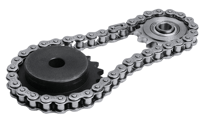
Most of ancient mills were located close to the water flow to avoid lost of energy and the difficulty of transport of mechanical rotation.In this days advancement in technology allow a use of various system of transmission of power from one location to another, but each one has its advantages and disadvantages. One of the most common way of transmission of power is belts and chains drive. Belts and chains are used to transmit power from one location to another like illustrated in the picture below:
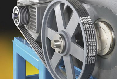
Chains and belts drive are one of the many option used in the transmission of rotational motion from one shaft to another. Either chain or belt is better than the other because depending on the application each one has it advantages and disadvantages. A description of each is necessary for a designer to choose which one to use depending on the resource available for the design.
Belts
Belts are defined as a looped strip of flexible material used to mechanically link two or more rotating shafts by means of pulleys. Belts are the most commonly used because of its low cost and simplicity of setting.
Pulley also called sheave is a wheel on an axle or a shaft with a groove rim around, in which a belt or cord passes, a pulley is designed to transfer power between the shaft and the belt or the cord.
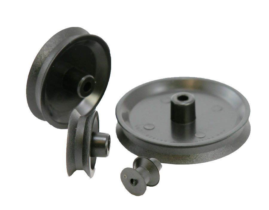
Pulley may be made of cast iron, sheet steel, or die-cast metal. Sufficient clearance must be provided at the bottom of the groove to prevent the belt from bottoming as it becomes narrower from wear.
| Advantages of belts | Disadvantages of belts |
|---|---|
| Low cost | Wearing and stretching of the belt |
| Simplicity of use | Velocity ratio vary because of the slip |
| Low maintenance cost | Operating temperature restricted from -35°C to 85°C |
| Damp noise and vibration | Short life of services compared to chain |
| Higher distance between shafts Recommended distance 3-10 meters | Limited speed around 35 meter per second |
| Service condition: Dry | Can not operate in wet condition: oil, grease etc. |
| Light weight | Idler pulley is necessary sometimes |
| Lubrication-free | Heat build up occurs |
Creep
In belt transmission is defined as the relative motion between the belt and the pulley due to the body slip. Depending on your design need there are a variety of belts on the market now but the most used are:
V-belt
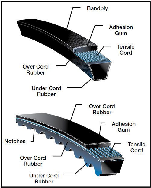
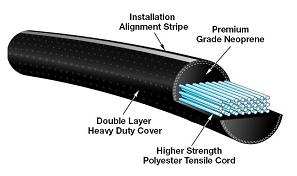
V-belt as shown are mostly used in workshop and factories.V-belts transmits action via the tapered side, the shape of the pulley groove and how the belt fits into this groove is important.V-belts are usually made of rubber with fibers embedded in it to strengthen the whole, in addition, tension members usually made of polyester increase the load carrying of the belts.
Round belt also called circular belt or rope are used when a great amount of power is to be transmitted.
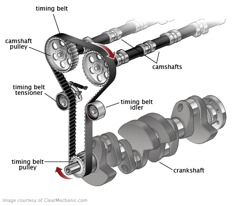
Timing belt are belts that have teeth to keep the power transmission process in synchronization.
Note how the axle of the shafts are parallel to each other
It is recommended that he tight side of the belt should be at the bottom, so whatever sag is present on the loose side will increase the arc of contact at the pulleys.
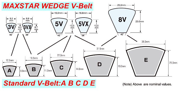
V-belts comes in five sizes identified by a letter from A to E.
Cross section and dimensions of multiple V-Belt
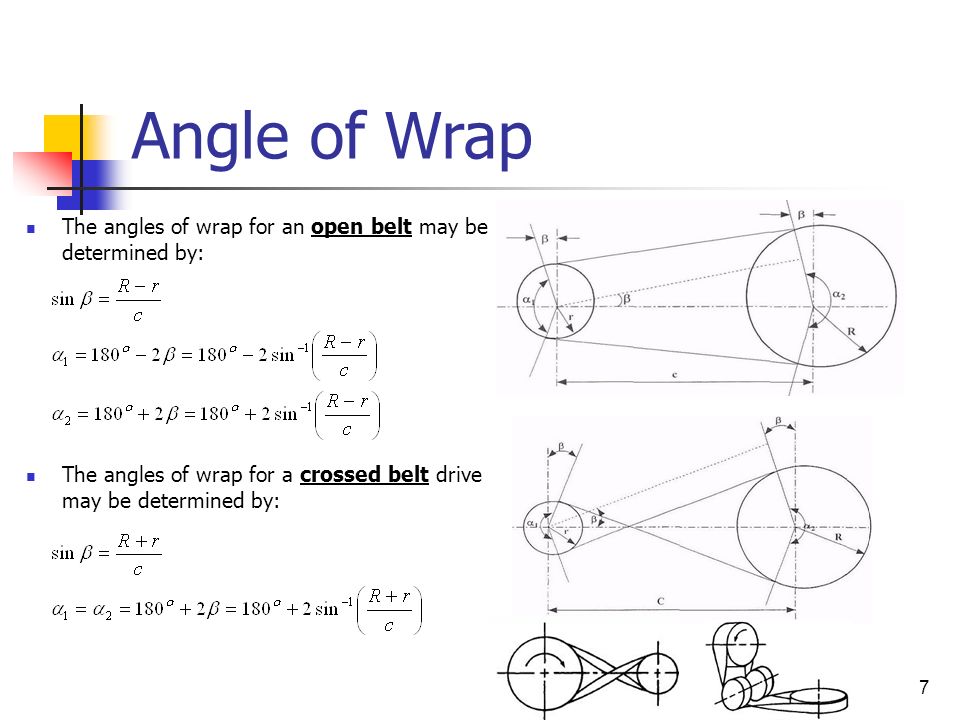
Angle of Wrap
Center Distance for V-belt drive
It is necessary to calculate the center distance c, between the pulleys
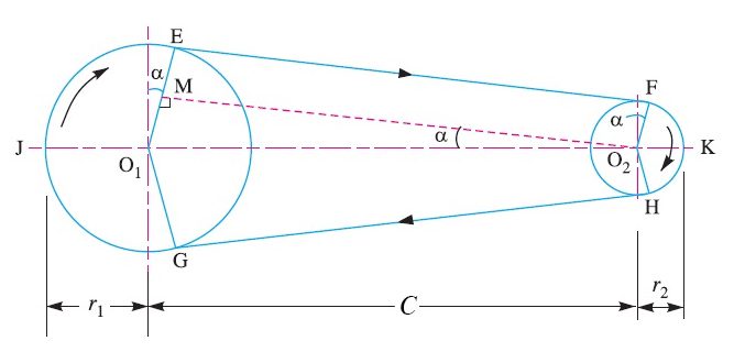

Where:
r1 is the radius of the small pulley
r2 is the radius of the big pulley
Previously we said that it was an excellent approximation because in reality the center distance should be deducted by including the angle of wrap called, in reality solve this equation for c
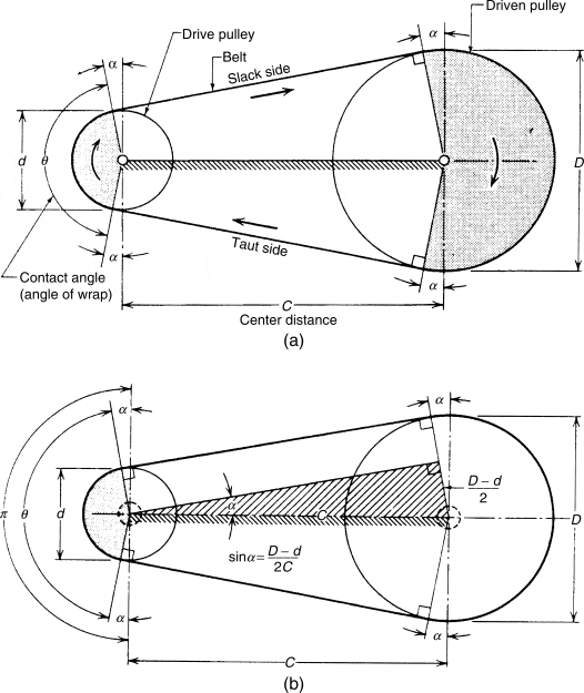
and the angle
can be determined
from
Horsepower transmitted by a belt
Example:
A 5V High capacity V-belt must deliver 12.5 output horsepower. The prime mover is an electric motor powering a piston pump running for 6 to 16 hours per day. Motor speed is 1750 rpm. Both driver and driven pulleys are 9.75 inches in diameter. The belt drive is expected to last for 20,000 hours. Select a belt, and the number of belts, that will result in a center distance as close to 30 inches as possible.
Solution:
To solve this problem you can draw a picture of two pulleys of the same diameter of 9.75 inches
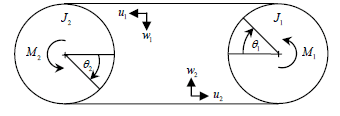
We assume that the diameter of the groove and the diameter of the pulley coincide together so we have only one diameter.
From the Table 30-4 below(Stock Drive Selection) we see that for a 5V belt the Long Life Service Factor (LLSF) is 1.2
LLSF=1.2
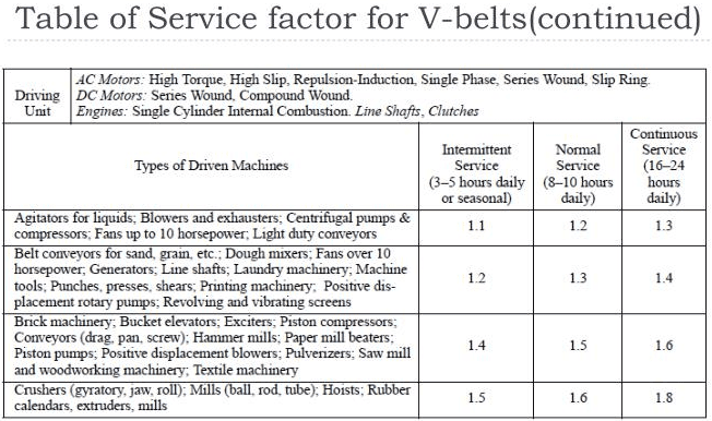
From the Table 30-5 below(Stock Drive Selection) we see that for a 5V belt the Service Factor (SF) is 1.5 for normal service operating from 6-16 hours, for Piston pump(Driven Machine Type)
SF=1.5
Table 30-4
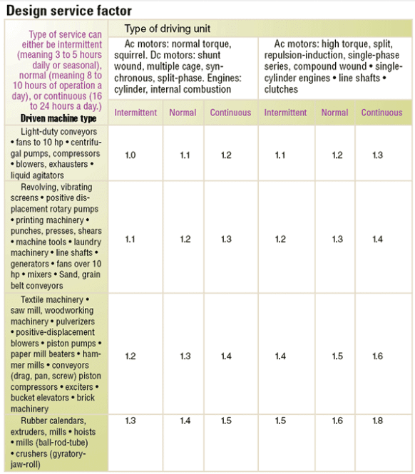
Table 30-5
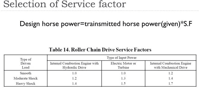
Table 6-3 Additional simplified table with different type of machine, different hours of service
We can say 25.8 hp per belt is our design
To find out how many belts needed to be used on this design, we need to find the ALCF (Arc length correct factor)number for this design on the table. To do so locate the length of of the center distance( 30 inches ) from Table 30-14 to 30-15, the center distance for both pulleys of 9.75 inches diameter is from 12.7 inches to 162.2 inches.Our center distance of 30 inches is between 29.7 inches and 32.2 inches. At 29.7 inches long the belt is 5V900, and at 32.2 inches long the belts is 5V950, both have the same ALCF of .95
Consequently the real hp transmitted per belt is calculated by:
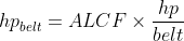

Our design require one belt, 5V900 if we choose a center distance of 29.7 inches or 5V950 if we choose a center of distance is 32.2 inches.
Chains
Chain have an initial cost of installation higher than belts design, but later, the maintenance cost is lower. Depending on your design need there are a variety of chains on the market now but the most used are:
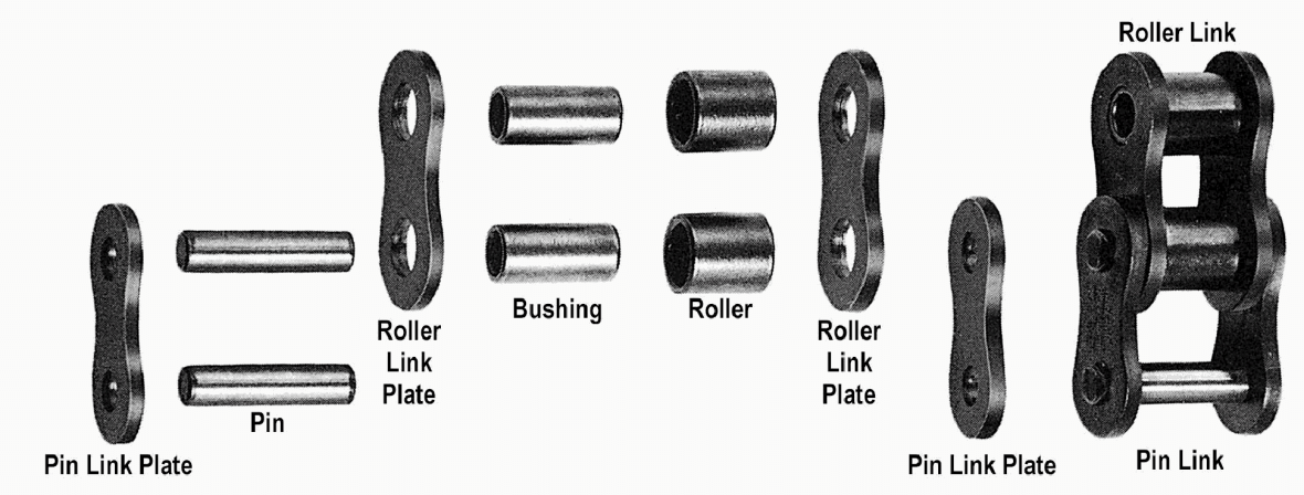
- Roller link
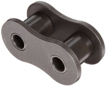
Roller chain is made up of roller links and pin links.
- Offset link
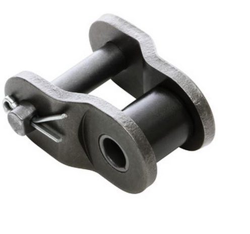
An offset link is a combination of a roller link and a pin link, this link is used where the chain length is an odd number of pitches.
- Spring clip connecting link is a standard for all single and multiple strand ANSI standard chain, 80 and below and British standard chain,16 B and below.
- Cotter pin connecting link is a standard for all single and multiple strand ANSI 100 and above and British standard chain, 20 B and above.
A Chain drive can also be used in:
- Conveying materials by attaching buckets,frames,pockets,o meshes to the chain.
- Timing process, many industry used chains drives to synchronize movements.
| Advantages of chains | Disadvantages of chains |
|---|---|
| Positive drive with no slip or creep | Higher initial cost of installation |
| Higher velocity ration up to 8:1 | Need regular lubrication |
| Higher transmission efficiency compared to belt up to 98% | Driven and driver shaft must be perfectly aligned and parallel |
| Low maintenance cost | No drive slip allowed |
| Can operate in dry and wet condition | Noisy and can cause vibration |
| Heavier than belts | Lower load capacity and service life than belt,gear drive |
| Smaller center to center distance up to 3 meters(118.11 inches) |
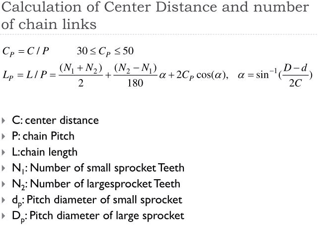
Determining the length of a chain:
- The chain length is given by the number of chain links and chain pitch.
- A sprocket is a toothed wheel upon which a chain rides, contrary to popular opinion, a sprocket is not a gear. Here a picture of a typical sprocket
Chain wheel with identical numbers of teeth z1= z2
- p is the pitch of the chain
- z1 is the number of teeth of the drive wheel
- z2 is the number of teeth of the drive wheel
- a is the approximation of the center distance in millimeters
- To find the number of links in the chain X, use X = (2ap)+z
- To find the center distance, use a = (X-z2)p
Chain wheel with different numbers of teeth z1≠z2
- To find the number of links in the chain X, use X = 2ap + z1+ z2+Aap
- A is defined as the compensation factor, a = (z1+ z2]2, also found in the Tables
- To find the center distance, use a = [2X – (z1+ z2)]Cp
- C is defined as the factor for center distance, also find in the Tables
Determination of dimension of the sprocket
- p is the pitch of the chain
- N is the number of teeth of the sprocket
- To find the pitch diameter, use p= p*sin(180N)
- To find the outside diameter, use o=P×[0.6+cot(180N)]
- To find the sprocket thickness, use e = 0.93×Roller width-0.006″
Roller Chain Selection Problem
A Roller Chain transmission is to be designed:
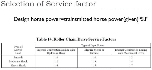
An electric motor is the prime mover, It operates at 1750 rpm, the required output shaft speed is 875 rpm, the horsepower required at the output of the transmission is 12.2. The operating conditions are such that they suggest moderate shock loading.
Using the attached table for ½ inch pitch Roller Chain, design at least two versions of the transmission.
1.One version is to be a single strand chain power transmission.
2.The second version is to be a multiple strand version.
Solution:
Given: SF1=1.3 (version1) ; SF2=1.7 (Version2)Values obtained from Table 6-7 below.
hpoutput=12.2
1: For a single strand on the smaller sprocket at 1750 rpm
The hpdesign=hpoutput*SF1=12.2*1.3=15.83hp
Let try N1=24 teeth
From the table 5-9, we see that at 1600 rpm hp=16.11 and at 1800 rpm the hp=15.03, to find the value of hp at 1750 rpm we used the method of…
hp=(1800-1750)rpm(1800-1600)rpm(16.11-15.03)hp=0.81hp
So with N1=24 teeth, the hpavailable=(16.11-0.81)hp=15.3 hp which is less than the hpdesign of 15.83hp
Let try N1=25 teeth
From the table 5-9, we see that at 1600 rpm hp=16.78 and at 1800 rpm the hp=15.98, to find the value of hp at 1750 rpm we used the method of… hp=(1800-1750)rpm(1800-1600)rpm(16.78-15.98)hp=0.75hp
So with N1=24 teeth, the hpavailable=(16.78-0.75)hp=16.03 hp which is more than the hpdesign of 15.83hp
From the speed ratio : N2/N1=1750rpm/875rpm=2, so N2=2N1=2*25=50 teeth So small sprocket 25 teeth and the big sprocket is 50 teeth for our design.
2: Let’s try a double strand, for double strand, from table 6-7A, the strand factor is 1.7
So as for the first case The hpdesign=hpoutput*SF1=12.2*1.3=15.83hp
So for a single strand 15.83*1.7=9.33 hp, so from this value we look at the table of single strand
Let try N1=17 teeth(small sprocket)
From the table …., we see that at 1600 rpm hp=10.69 and at 1800 rpm the hp=8.96, to find the value of hp at 1750 rpm we used the method of……
hpavailable=(1800-1750)rpm(1800-1600)rpm(10.69-8.96)hp=9.39hp
The hpavailable is greater than the hpdesign so our design is functional.
In conclusion each drive have its own set of advantages and disadvantages, sometimes a combination of both can suit the design needed.
Applications
Steps to approach the design
Types of belts drive
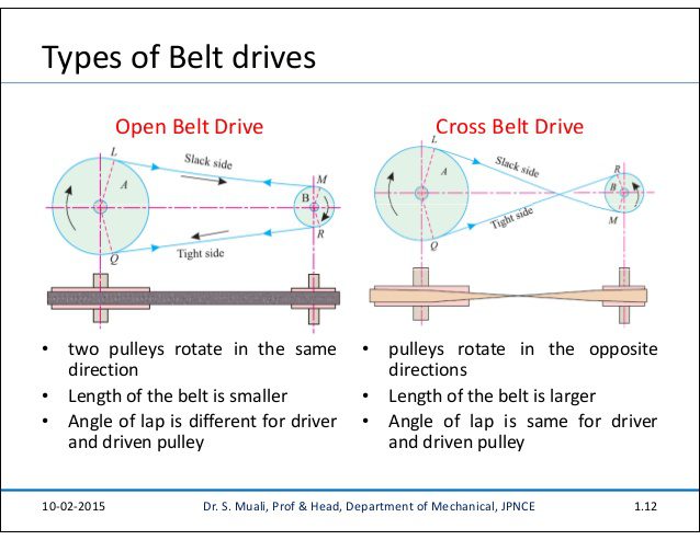
Belt drives are divided into two type open belt drive and cross belt drive as shown in the picture bellow:
- In the open belt drive both pulley rotate in the same direction making one side of the belt more tight and the opposite side sag
- In the cross belt drive pulley rotate in opposite direction, the belt wraps the pulleys more which produce more power transmitted.
For more examples of calculation on belt, use this link bellow:
Resources and References:
- http://www.directindustry.com/prod/timken-belts/product-5607-39560.html
- https://repairpal.com/estimator/timing-belt-replacement-cost
- https://www.powertransmission.com
- https://www.gates.com/us/en/power-transmission/v-belts/round-belts.html
- Slide Player
- http://www.tankchain.com/shop/
- https://www.motion.com/products/sku/00151703
- https://www.homesciencetools.com/product/mini-pulley-set/
- https://tokiwa.trustpass.alibaba.com
- https://www.slideserve.com/lavender/machine-element-design
- HZPT