Motors

DC Motors

Brushed DC Motors Direct-current motors are used where a wide range of precise torque and speed control is required to match the needs of the application. Such applications include cranes, conveyors, and elevators. Direct-current motors are not used as much as alternating current types because all electric utility systems deliver alternating current. For special applications, however, it is advantageous to transform the alternating current into direct current in order to use DC motors. The construction of a DC motor is considerably more complicated and expensive than that of an AC motor, primarily because of the commutator, brushes, and armature windings. Maintenance of the brush/commutator assembly found on DC motors is significant compared to that of AC motor designs. An AC induction motor requires no commutator or brushes, and most use cast squirrel-cage rotor bars instead of wound copper wire windings. There are several types of DC motors, classified according to field type. These are permanent magnet, series, shunt, and compound. Motor speed, torque, and power are important parameters used to predict DC motor performance: Speed: Refers to the rotational speed of the motor’s shaft and is measured in revolutions per minute (rpm). Torque: Refers to the turning force supplied by the motor’s shaft. Torque consists of force acting on a radius. The standard unit of torque is Nm. Power: Refers to the rate at which work is done. It is usually stated in horsepower. One horsepower is equivalent to 746 watts of electrical power. Therefore, you can use watts to calculate horsepower and vice versa. Permanent-Magnet DC Motors Permanent-magnet DC motors use permanent magnets to supply the main field flux and electromagnets to provide the armature flux. Movement of the magnetic field of the armature is achieved by switching current between coils within the motor. This action is called commutation. Brushes, in contact with the commutator, carry current to the coils. PM motors produce high torque compared to wound-field motors. However permanent magnet motors are limited in load-handling ability and for this reason used mainly for low-horsepower applications. The direction of rotation of a permanent-magnet DC motor is determined by the direction of the current flow through the armature. Reversing the polarity of the voltage applied to the armature will reverse the direction of rotation. Variable-speed control of a PM motor is accomplished by varying the value of the voltage applied to the armature. The speed of the motor varies directly with the amount of armature voltage applied. The higher the value of the armature voltage, the faster the motor will run.
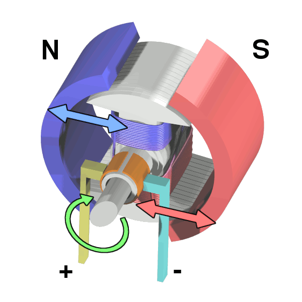
Workings of a brushed electric motor with a two-pole rotor (armature) and permanent magnet stator

Workings of a brushed electric motor with a two-pole rotor (armature) and permanent magnet stator
source: https://commons.wikimedia.org/wiki/File:Electric_motor_cycle_2.png

Series DC Motor

A series-wound DC motor has a low resistance field and low resistance armature circuit. Because of this, when voltage is first applied to it, the current is high (I = E/R). The advantage of high current is that the magnetic fields inside the motor are strong, producing high torque (turning force), so it is ideal for starting very heavy mechanical loads. The speed varies widely between no load and rated load. Therefore, these motors cannot be used where a constant speed is required with variable loads. Also the motor runs fast with a light load (low current) and runs substantially slower as the motor load increases. Because of their ability to start very heavy loads series motors are often used in cranes, hoists, and elevators, which can draw thousands of amperes on starting. Caution: The no-load speed of a series motor can increase to the point of damaging the motor. For this reason, it should never be operated without a load of some type coupled to it. Shunt DC Motor When the motor is starting and speed is very low, the motor has very little torque. After the motor reaches full rpm, its torque is at its fullest potential. One of the main advantages of a shunt motor is its constant speed. It runs almost as fast fully loaded as it does with no load. Also, unlike the series motor, the shunt motor will not accelerate to a high speed when no load is coupled to it. Shunt motors are particularly suitable for applications such as conveyors where constant speed is desired and high starting torque is not needed. Compound DC Motor A compound-wound DC motor is a combination of the shunt-wound and series-wound types. The shunt field gives this type of motor the constant-speed advantage of a regular shunt motor. The series field gives it the advantage of being able to develop a large torque when the motor is started under a heavy load. This motor is normally connected cumulative-compound so that under load the series field flux and shunt field act in the same direction to strengthen the total field flux. These motors are generally used where severe starting conditions are met and constant speed is required at the same time.

DC Servo Drives The precise meaning of the term ‘servo’ in the context of motors and drives is difficult to pin down. Broadly speaking, if a drive incorporates ‘servo’ in its description, the implication is that it is intended specifically for closed-loop or feedback control, usually of shaft torque, speed, or position. Early servomechanisms were developed primarily for military applications, and it quickly became apparent that standard DC motors were not always suited to precision control. In particular high torque to inertia ratios were needed, together with smooth ripple-free torque. Motors were therefore developed to meet these exacting requirements, and not surprisingly they were, and still are, much more expensive than their industrial counterparts. Whether the extra expense of a servo motor can be justified depends on the specification, but prospective users should always be on their guard to ensure they are not pressed into an expensive purchase when a conventional industrial drive could cope perfectly well. The majority of servo drives are sold in modular form, consisting of a high-performance permanent magnet motor, often with an integral tachogenerator, and a chopper-type power amplifier module. The drive amplifier normally requires a separate regulated DC power supply, if, as is normally the case, the power is to be drawn from the AC mains. Continuous output powers range from a few watts up to perhaps 2–3 kW, with voltages of 12, 24, 48, and multiples of 50 V being standard.
Position control

As mentioned earlier many servo motors are used in closed-loop position control applications, so it is appropriate to look briefly at how this is achieved. In the example shown in figure, the angular position of the output shaft is intended to follow the reference voltage (uref), but it should be clear that if the motor drives a toothed belt linear outputs can also be obtained. The potentiometer mounted on the output shaft provides a feedback voltage proportional to the actual position of the output shaft. The voltage from this potentiometer must be a linear function of angle, and must not vary with temperature, otherwise the accuracy of the system will be in doubt. The feedback voltage (representing the actual angle of the shaft) is subtracted from the reference voltage (representing the desired position) and the resulting position error signal is amplified and used to drive the motor so as to rotate the output shaft in the desired direction. When the output shaft reaches the target position, the position error becomes zero, no voltage is applied to the motor, and the output shaft remains at rest. Any attempt to physically move the output shaft from its target position immediately creates a position error and a restoring torque is applied by the motor.
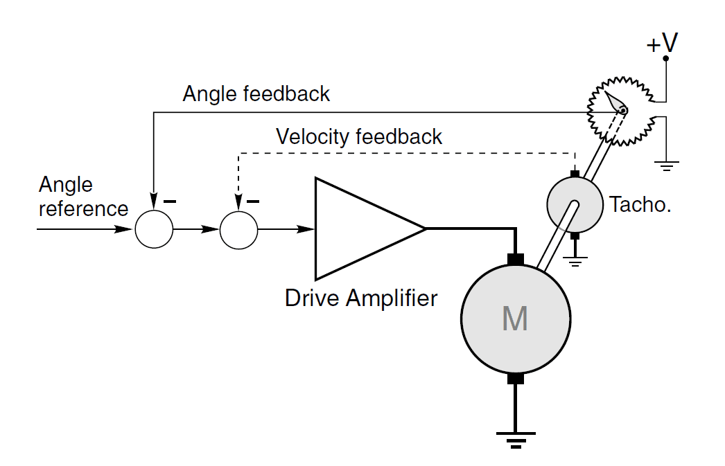
Closed-loop angular position control using DC motor and angle feedback from a servo-type potentiometer

Closed-loop angular position control using DC motor and angle feedback from a servo-type potentiometer
Source: Electric Motors and Drives by Austin Hughes

Control arrangements for DC drives

The most common arrangement, which is used with only minor variations from small drives of say 0.5 kW up to the largest industrial drives of several MW, is the so-called two-loop control. This has an inner feedback loop to control the current (and hence torque) and an outer loop to control speed. When position control is called for, a further outer position loop is added. A two-loop scheme for a thyristor DC drive is discussed first, but the essential features are the same in a chopper-fed drive. In order to simplify the discussion we will assume that the control signals are analogue, although in all modern versions the implementation will be digital, and we will limit consideration to those aspects which will be beneficial for the user to know something about. In practice, once a drive has been commissioned, there are only a few adjustments to which the user has access. To appreciate the overall operation of a two-loop scheme we can consider what we would do if we were controlling the motor manually. For example, if we found by observing the tachogenerator that the speed was below target, we would want to provide more current (and hence torque) in order to produce acceleration, so we would raise the armature voltage. We would have to do this gently, however, being mindful of the danger of creating an excessive current. We should keep our eye on the ammeter at all times to avoid blowing up the thyristors; and as the speed approached the target, we would trim back the current (by lowering the applied voltage) so as to avoid overshooting the set speed. Actions of this sort are carried out automatically by the drive system.
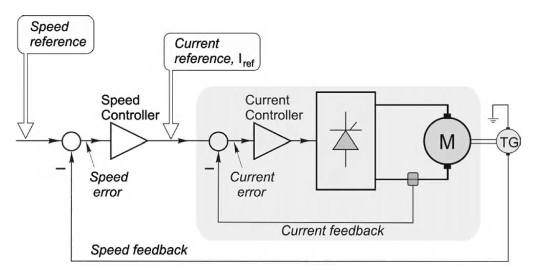
Schematic diagram of analogue controlled-speed drive with current and
speed feedback control loops

Schematic diagram of analogue controlled-speed drive with current and speed feedback control loops
source: Electric Motors and Drives by Austin Hughes

A standard DC drive system with speed and current control is shown. The primary purpose of the control system is to provide speed control, so the ‘input’ to the system is the speed reference signal on the left, and the output is the speed of the motor (as measured by a tachogenerator) on the right. As with any closed-loop system, the overall performance is heavily dependent on the quality of the feedback signal, in this case the speed-proportional voltage provided by the tachogenerator. It is therefore important to ensure that the tacho is of high quality (so that, for example, its output voltage does not vary with ambient temperature, and is ripple-free) and as a result the cost of the tacho often represents a significant fraction of the total cost.

Electric Motor Basics

When a current-carrying conductor is placed in a magnetic field, it experiences a force. The magnitude of the force depends directly on the current in the wire, and the strength of the magnetic field, and the force is greatest when the magnetic field is perpendicular to the conductor.

Magnetic Field

The notion of a ‘magnetic field’ surrounding a magnet is an abstract idea that helps us understand the mysterious phenomenon of magnetism. The dotted lines in the figure shown are referred to as magnetic flux lines, or simply flux lines.

Magnetic Flux

Along with showing direction, the flux plots also convey information about the intensity of the magnetic field. To achieve this, we introduce the idea that between every pair of flux lines there is a same ‘quantity’ of magnetic flux. We call this magnetic flux density (B). When the flux lines are close together, the ‘tube’ of flux is squashed into a smaller space, whereas when the lines are further apart the same tube of flux has more breathing space. The flux density (B) is simply the flux in the ‘tube’ (Φ) divided by the cross sectional area (A) of the tube, i.e.  The flux density is a vector quantity. Near the poles of the magnet in the figure, for example, the flux density will be large (because the flux is squashed into a small area), whereas in the middle and far out from the body of the magnet the flux density will be small (see figure below).
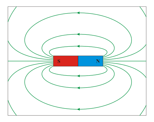
Example of dipole. Magnetic field around a bar magnet.

Example of dipole. Magnetic field around a bar magnet.
source: https://commons.wikimedia.org/w/index.php?title=File:DipolMagnet.svg

Units

In the SI system, the unit of magnetic flux is the weber (Wb). If one weber of flux is distributed uniformly across an area of 1m2 perpendicular to the flux, the flux density is clearly one weber per square metre (Wb/m2). This was the unit of magnetic flux density until about 40 years ago, when it was decided that one weber per square meter would henceforth be known as one tesla (T), in honour of Nikola Tesla who is generally credited with inventing the induction motor.

Magnetomotive Force

The ability of the coil to produce flux is quantified in terms of its magnetomotive force (MMF). The MMF of the coil is simply the product of the number of turns (N) and the current (I), and is thus expressed in ampere-turns. We can make use of an equivalent ‘magnetic Ohm’s law’ by introducing the idea of reluctance (R). The reluctance gives a measure of how difficult it is for the magnetic flux to complete its circuit, in the same way that resistance indicates how much opposition the current encounters in the electric circuit. The magnetic Ohm’s law is 

Production of Force

The force on a wire of length l, carrying a current I and exposed to a uniform magnetic flux density B throughout its length is given by the simple expression

F = BIl

where F is in newtons when B is in tesla, I in amperes, and l in metres.

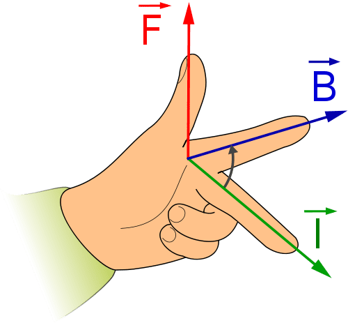
Fleming’s left hand rule
The direction of force can be represented by Fleming’s left hand rule:

  • The F (Thumb) represents the direction of Force of the conductor
  • The B (Forefinger) represents the direction of the Magnetic field
  • The I (Center finger) represents the direction of the Current
Fleming’s left hand rule

Selecting DC Motors

This page is continued from DC Motors DC Motor Rating DC Motors are typically rated in terms of :

  • Rated voltage: The operating voltage on the input side of the motor.
  • Rated power: Power (in horsepower – hp or watts) that the motor is designed to deliver to the load (i.e., output power) for continuous operation.
    (Note that 1 hp = 746 W)
  • Rated speed: Speed (in revolutions per minute, denoted by r/min or rpm) for which the motor is designed to operate for continuous operation.
  • Rated load: The load which the motor is designed to carry for (theoretically) infinite period of time. “Full load” or “rated load” operating condition refers to the operation of motor when it is delivering rated power to the load.

Note: A motor may not always operate at its rated power and/or speed. Operation above these values is not advisable due to overloading.

Selecting a DC motor to accurately meet a set of requirements requires careful attention. Having to choose between brush-type or brushless motors can complicate the selection. Even experienced designers may sometimes overlook critical motor parameters and find problems after the system is up and running. In the worst case, starting over may be the only alternative. Since we only need to select a motor without learning its construction or working principle, we can use an expedient procedure select DC motors. This procedure is based upon an accurate definition of the target system parameters and designer experience. DC motor selection parameters Several motor parameters are the same for both brush-type and brushless DC motors. One of these is motor constant, Km. It is important but widely overlooked. It is used during motor sizing because it is a figure of merit of the motor power-to-torque ratio. Km is proportional to the ratio of peak torque, Tp, to peak power, Pp, at stall: Km = Tp / PpKm is also proportional to the ratio of torque sensitivity, Kt, to motor terminal resistance, Rm:Km = Kt / Rm. After the required Km has been determined, a candidate motor with this value or greater is selected from a catalog. The motor is only a candidate at this point because other factors must be determined. As the design selection progresses, some trade-offs typically take place. For example, the motor must also satisfy physical size and inertia requirements.

DC Motor (Separately excited or Permanent Magnet)
Drive typeSingle QuadrantFour QuadrantDC Chopper
ConverterSingle or three phase fully (or half) controlled thyristor bridgeDual single/three phase fully controlled thyristor bridgeDC Chopper
Torque/Speed RangeMotoring in one direction (Braking in other direction)Motoring and braking in both directions2 or 4 quadrant versions
Speed controlClosed loop control of armature voltage with inner current control loop
Torque controlClosed loop control of armature current
Ratings10 W to 5 MW (Fractional HP to 7000 HP)0.5 to 5 kW (0.7 to 7 HP) Traction > 500 kW
Max PowerAvailable to multi-MW ratings, but motor limitations restrict the product of Power and Speed to 3 × 10⁶ kW.rev/min
Min speedGood control down to standstill
Notable featuresSeparately excited motors often used above base speed in constant-power modeDC to DC conversion
Fast torque reversalsSmooth torque possible
AdvantagesLow cost controllerRelatively simple technologyGood dynamic performanceRelatively simple technology
DisadvantagesBrush gear maintenancePossible failure on supply lossInstability on fan/pump type loadsLow motor IP rating

General Application Considerations

  • Regenerative operation and braking
    All motors are inherently capable of regenerative operation, but in drives the basic power converter as used for the ‘bottom of the range’ version will not normally be capable of continuous regenerative operation. The cost of providing for fully regenerative operation is usually considerable, and users should always ask the question ‘do I really need it?’
    In most cases it is not the recovery of energy for its own sake which is of prime concern, but rather the need to achieve a specified dynamic performance. Where rapid reversal is called for, for example if kinetic energy has to be removed quickly, this implies that the energy is either returned to the supply (regenerative operation) or dissipated (usually in a braking resistor). An important point to bear in mind is that a non-regenerative drive will have an asymmetrical transient speed response, so that when a higher speed is demanded, the extra kinetic energy can be provided quickly, but if a lower speed is demanded, the drive can do no better than reduce the torque to zero and allow the speed to coast down.
  • Duty cycle and rating

Selecting Stepper Motors

Motors are a very common component in many systems. To function properly, their selection requires a careful step by step process that relies heavily on the intended operation of the motor. While designing your system, it is advantageous to begin with the end in mind. Therefore, before motor selection can begin, it is beneficial to define what the motor will have to do, the performance goals of the motor. Understanding these parameters will help the selection process by keeping the focus on what your system must achieve, and in turn can help you to better define motor technical requirements. This page will help you focus on your design goals and quicken the process of purchasing the right motor from a catalogue. Start by defining the function of the motor and its performance requirements.

Performance Goals

Although the performance targets are in terms of maximum velocity and maximum acceleration, the motors can’t be characterized by these variables because other factors such as weight of the system greatly affect a motor’s output. Instead of velocity and acceleration, motors are characterized by their rotational speed (n) and the torque (T) that they can provide. Both of these can be related to the velocity and acceleration of the robot using the equations below.

Speed

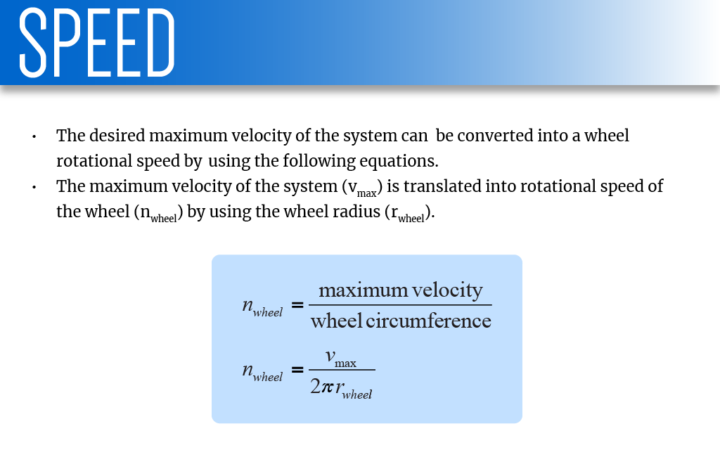
Let’s assume a stepper motor is being used to rotate a wheel which supports the system. The desired maximum velocity of the system can be converted into a wheel rotational speed by using the following equations. Let’s say we want the system to move at a speed of 1.2 m/s and the radius of the wheel is 0.05 m. The maximum velocity of the system (vmax) is translated into rotational speed of the wheel (nwheel) by using the wheel radius (rwheel).

image showing calculation for speed
This calculated rotational speed is the desired operating wheel speed for the system

This calculated rotational speed is the desired operating wheel speed for the system. However, when selecting a motor, motors’ data sheets give ratings for a “No-Load” speed (n0) or the maximum rotational speed of the motor with nothing attached to it, i.e. having “no-load.” The motor you select will require a rated “No-Load” speed greater than your calculated operating speed because when a physical load is placed on the motor, the motor speed will naturally slow down. Physical load on the motor can more accurately be stated as the amount of force required to maintain the target velocity (vmax) and achieve the target acceleration (amax). These forces will then need to be translated into a torque (T) requirement for the motor. Once a torque requirement and the desired operating wheel speed are known, you will have your initial mechanical requirements to begin identifying options for your motor.


Torque

The value of the torque requirement will be a little more difficult to accurately predict than the desired operating wheel speed. During steady state constant velocity operation, the motor requires torque to overcome the friction in the system such as between motor bearings, gears or other contacting surfaces and any longitudinal component of the weight vector such as going up/down an incline. Because of the difficulty of obtaining many of these values, some assumptions will be required to get the motor selection process started.

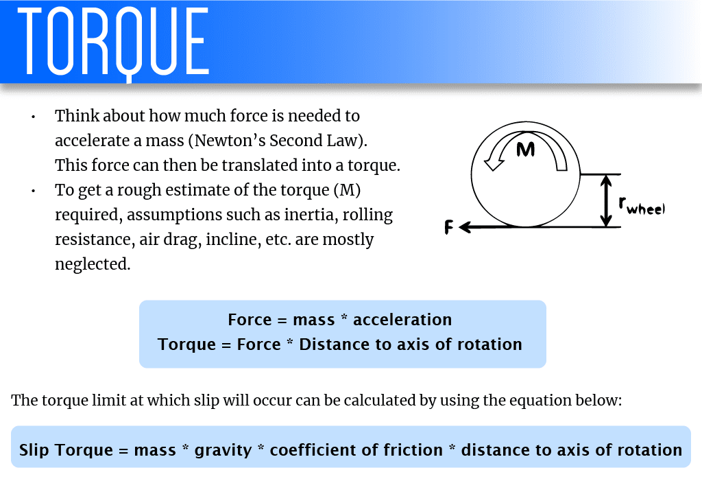
graphic representation for torque calculations

To understand torque, think about how much force is needed to accelerate a mass. We can find this using Newton’s Second Law. This force can then be translated into a torque. Let’s say that the mass of your system is 10 kg, and to accelerate it at 2 m/s2, a force of 20N is required. F = 10kg x 2m/s² = 20N Torque is the product of force and distance to the axis of rotation. Earlier we have assumed that a wheel of radius 5 cm is connected to your stepper motor. Then the torque required for the system to keep accelerating at 2 m/s2 is 1 Nm. Based on this result, the motor chosen should have a torque provided to the wheel greater than 1 Nm considering other factors such as friction and air resistance. 


Extra torque when scaling inclines
If your stepper motor is going to be used to power wheels which be going up an inclined surface, it means the motor has to work against gravity. Use the following formula to calculate the extra force required. In the example, the force required by the same 10 kg system to accelerate at 2 m/s2 while going up an incline of 10° is 45.6 N. 

F = 10kg x 9.81m/s² + (15kg x 9.81m/s² x sin 10°)


Traction limited torque / Slip torque
Before confirming the above calculated value as the target torque, it is important to understand the maximum torque that each wheel can transmit. This is known as the traction limited torque. If the motor can produce more torque than the wheel can transmit, then the wheel will slip on the ground. To perform a quick check of the traction limits of wheels, the assumption will be made that there is no weight transfer due to acceleration. This is rarely true in practice, but a conservative estimate of the wheel’s coefficient of friction with the intended ground can help overcome the weakness in this approximation. The torque limit at which wheel slip will begin to occur can be calculated using the equation shown. In the example, the friction coefficient is taken as 0.6 which results in a traction torque of 2.95 Nm.

Ttrac = 10kg x 9.81 m/s² x .06 x 0.05m

Since the maximum torque our system requires is 2.28 Nm and the slip torque occurs at 2.95 Nm, our system remains unaffected.


Power
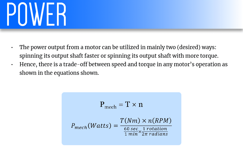
The speed and torque requirements you determined earlier are also used to determine a power requirement for your motor. All motors are only able to output a maximum amount of power denoted by Pmech, max. The power output from a motor can be utilized in mainly two (desired) ways: spinning its output shaft faster or spinning its output shaft with more torque. Hence, there is a trade-off between speed and torque in any motor’s operation as shown in the equations below.

graphic representation for equations that represent power

Conclusion
We now have:

  • The desired wheel operational speed, n (RPM) = 229.2 RPM
  • The required torque target from the corresponding acceleration target at that operational speed T = 2.28 Nm
  • Confirmation that the torque target will not cause wheel slip, 2.28 Nm ≤ 2.95 Nm

Stepper motor purchasing
You can purchase stepper motors from the following places on the web: https://www.pololu.com/category/87/stepper-motors https://www.mcmaster.com/motors https://www.automationtechnologiesinc.com/products-page/stepper-motors/

Stepper Motors

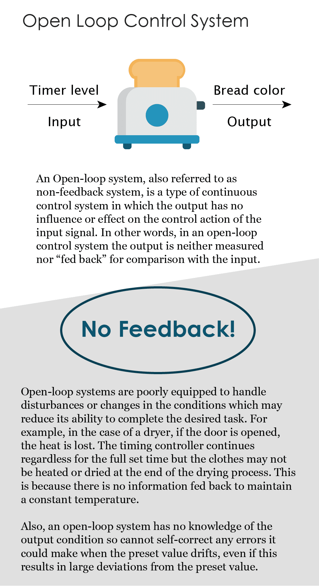
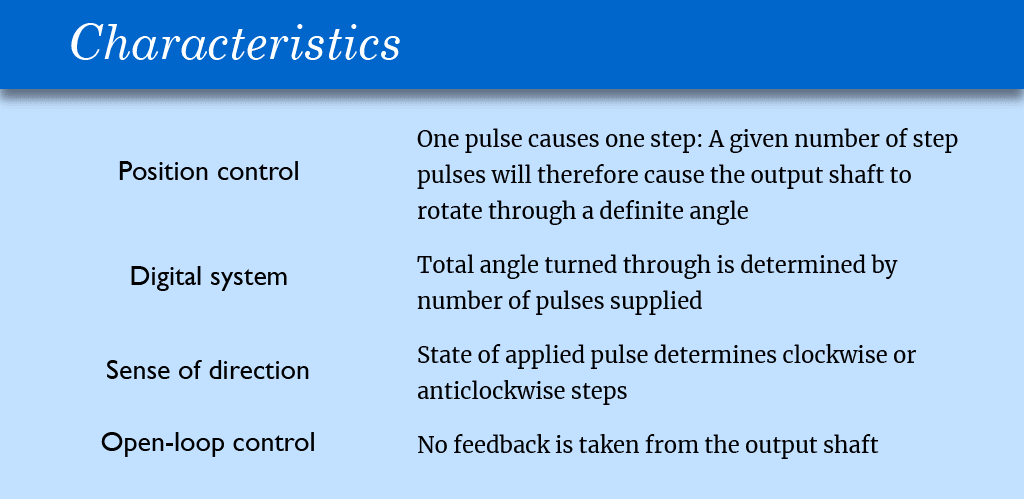
A stepper motor or step motor or stepping motor is a brushless DC electric motor, which means it rotates continuously when a DC voltage is applied to their terminals. They are typically used in open-loop control systems. Before learning more about stepper motors, it is important to understand open-loop control. Here’s a brief introduction.

Graphic representation for an open loop system

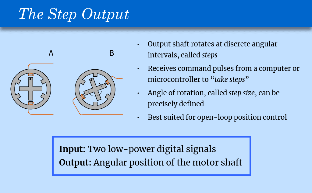
Stepper motors continued The unique feature of stepper motors is step control. The output shaft rotates in a series of discrete angular intervals, or steps, one step being taken each time a command pulse is received. When a definite number of pulses has been supplied, the shaft will have turned through a known angle, and this makes the motor well suited for open-loop position control.

Graphic representation for a Step Output

A stepper motor with a soft iron rotor, with active windings shown. In ‘A’ the active windings tend to hold the rotor in position. In ‘B’ a different set of windings are carrying a current, which generates torque and rotation.
Image source: https://commons.wikimedia.org/wiki/File:Stepper_motor.svg Step Speed Each step is completed very quickly, usually less than a millisecond; and when a large number of steps is called for the step command pulses can be delivered rapidly, sometimes as fast as several thousand steps per second. At these high stepping rates the shaft rotation becomes smooth, and the behavior resembles that of an ordinary motor.

Graphic representation for characteristics for stepper motors

As a general guide we can assume that the torque and power of a stepping motor will be similar to the torque and power of a conventional totally enclosed motor of the same dimensions and speed range. Step angles are mostly in the range 1.8° – 90°, with torques ranging from 1 μNm up to perhaps 40 Nm in a motor of 15 cm diameter suitable for a machine tool application where speeds of 500 rev/min might be called for, but the majority of applications use motors which can be held comfortably in the hand.

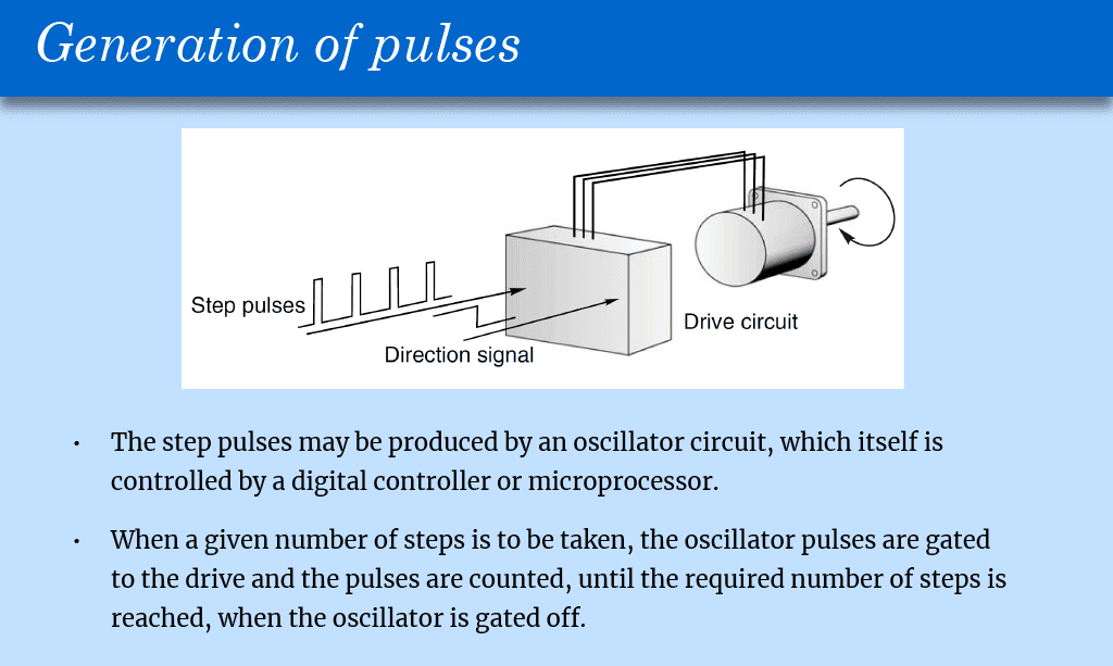
Graphic Representation for Generation of Pulses

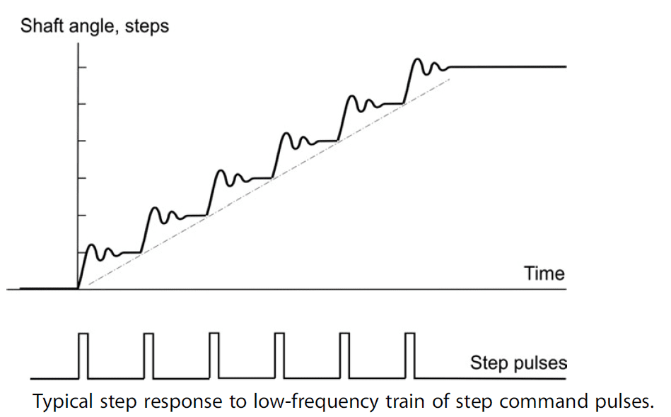
The following figure illustrates a six-step sequence. There are six step command pulses, equally spaced in time, and the motor takes one step following each pulse.

Chart for a step response to low-frequency train of step command pulses

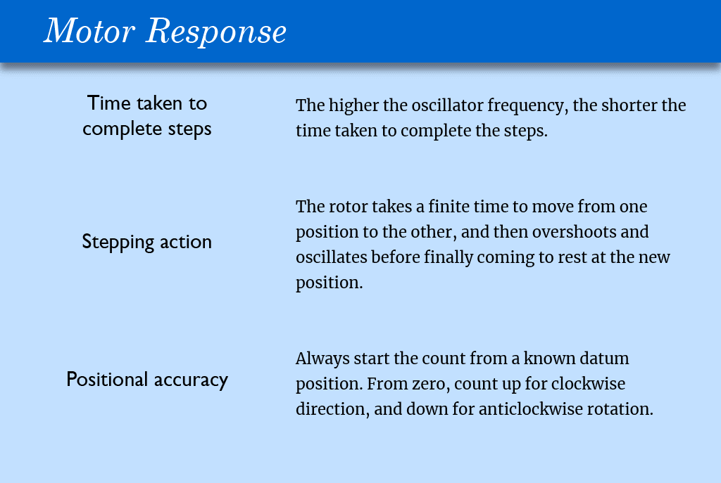
Three important general features can be identified with reference to the above figure. First, although the total angle turned through (six steps) is governed only by the number of pulses, the average speed of the shaft (which is shown by the slope of the broken line in the figure) depends on the frequency. The higher the frequency, the shorter the time taken to complete the six steps. Secondly, the stepping action is not perfect. The rotor takes a finite time to move from one position to the next, and then overshoots and oscillates before finally coming to rest at the new position. Overall single-step times vary with motor size, step angle and the nature of the load, but are commonly within the range 5–100 ms. This is often fast enough not to be seen by the unwary newcomer, though individual steps can usually be heard; small motors ‘tick’ when they step, and larger ones make a satisfying ‘click’ or ‘clunk’. Thirdly, in order to be sure of the absolute position at the end of a stepping sequence, we must know the absolute position at the beginning. This is because a stepping motor is an incremental device. As long as it is not abused, it will always take one step when a drive pulse is supplied, but in order to keep track of absolute position simply by counting the number of drive pulses (and this is after all the main virtue of the system) we must always start the count from a known datum position. Normally the step counter will be ‘zeroed’ with the motor shaft at the datum position, and will then count up for clockwise direction and down for anticlockwise rotation.

Graphic Representation for motor responses